circuit bending the casio pt-100
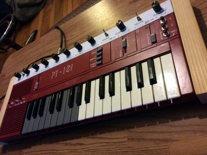
I've had this keyboard lying around for years (I don't remember where or when I got it), and after my first bend I wanted to dive a little deeper.
After experimenting I read the writeup at tablehooters and found the chord modes, rhythm select, and sustain mode. I find the prospect of adding functionality that exists in the hardware but simply wasn't built into the keyboard really exciting. I couldn't really add more keys and the extra tone selection seemed convoluted. I also read the noystoise article which hinted at a tone select function but couldn't find it for the life of me. I did discover a fill button which I added on the far left.
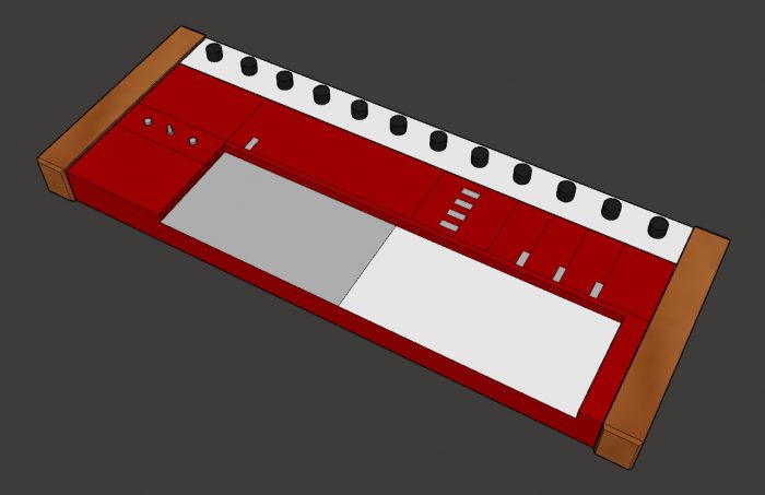
This is the final computer model I'd made after many iterations, including one with a banked panel and many more switches and knobs. There's a deceivingly trim-pot-type element close to the main IC which turned out to be a tank circuit so the pitch knob was out. I was also hoping to replace the six position volume slider with a knob but upon testing it picked up some conservative talk radio. After eliminating some similar bends and discovering the switched potentiometer trick--see below--I narrowed it down to 12 knobs on the upper panel.
In progess:
When I started this project I had very few tools and parts. So while I was waiting for the mail I was estimating the resistance range needed in a bend by the amount my 50k pot was turned. This article led me to believe I could simply limit the range of a pot by adding the appropriate resistors in parallel. That's true, but what's left out there is that doing so changes the relationship between knob turn and resistance to a more logarithmic one (see here). So using resistors to change a 50k pot to a 20k pot actually doesn't add that much control to the sound (depending) and could even make it worse.
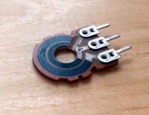
Many of the bends I found required switches but after learning you could hack a potentiometer to also act as a switch (see here and the picture) I thought it would be fun and a little nicer looking.
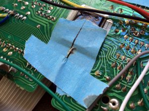
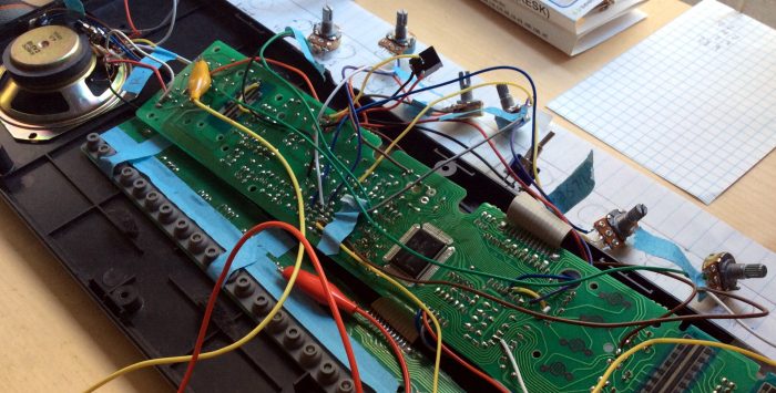
The hardest thing to solder by far was the reverb switch (called "sustain" in the tablehooters article). This involved soldering directly to an unconnected lead on the main IC, pin 90. I could always de-solder it if I messed up so the bigger challenge to me was getting that much heat near the main IC without fucking up the chip. Maybe it was unwarranted. I ended up using tape and then super gluing the insulated portion of wire directly to the PCB so it wouldn't yank loose...
Toward the end of assembly I noticed a few of the pots didn't have great connections and a couple pots didn't quite do what they had when tested. I re-soldered and fiddled hoping for the best, but really I felt like that was part of the whole putting-a-shit-ton-of-wires-and-knobs-in-old-electronics deal. Even when it's finally assembled the process of discovery continues.
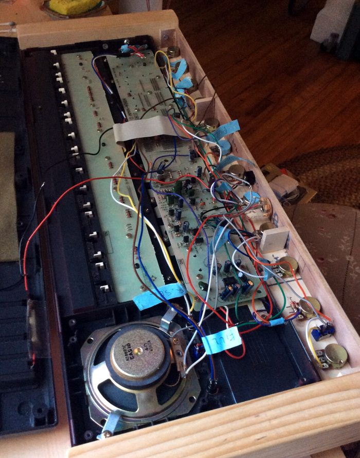
Here it is before I squeezed on the back cover:
Overall I'm very happy with this project. I made a lot of tiny compromises, learned a lot, it's fun to play, and I didn't totally break anything! I consider that a success.