I made some tapes again
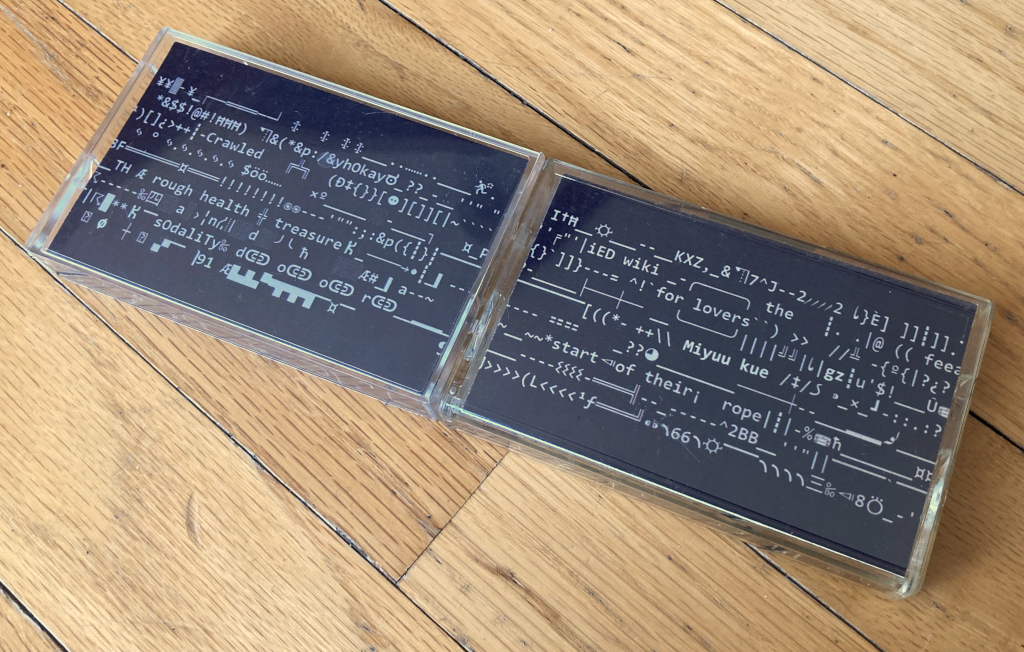
These tapes were recorded over at least 5 years. I don’t record much at all but when I do it’s usually from my modular synth straight into a 4-track. The part I like most about synths isn’t necessarily the music but also the process of building or modding. Reading about the circuits and what strangers have gleaned is more than interesting, and then incorporating that (or “synthesizing” it, haha) into a larger system is really fun and rewarding for me. There’s really no end to the lessons learned.
All that is a solo activity in general (what people share online is hardly social for me) so it’s great to meet up with friends irl–of any and all levels of familiarity with electronics–and share what we can. Repairing electronics for people is another great way to come together. And making tapes is another.
The liner notes: All sounds here were created and recorded using electronics that were either built, modified, or repaired by yours truly. This album wouldn’t exist without the consistent encouragement of my friends to record. Thanks for listening!
Sometimes working with electronics is therapeutic and refreshing, and sometimes it’s a distraction or a hiding place. But it always involves relationship somehow, and exploration, and I love that.
[[If you like your music digitally I’d be happy to share a link to a download, just let me know!]]
changing my keyboard part 2
My first foray into building that ergonomic split keyboard was excellent, more fun than I’d expected even. Playing with the layout, experimenting with placement and posture, and the sheer utility were all great. I adjusted to the ortholinear layout and thumb row keys better than I’d anticipated. I am a consistent hot key user, so an alt-tab or ctrl-z equivalent wasn’t a big stretch, but adjusting to multiple uses per key was a little weird–still is.
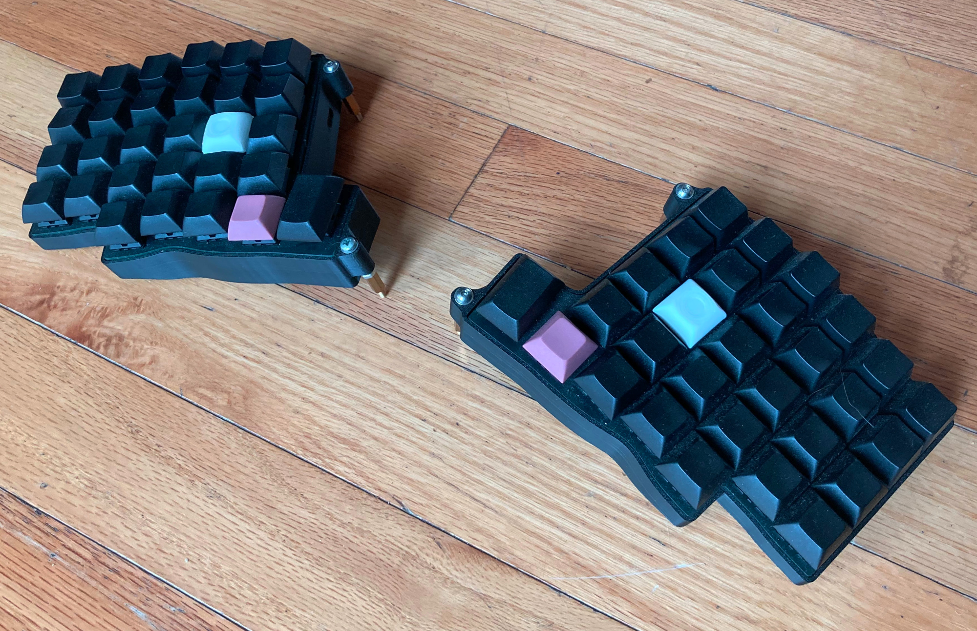
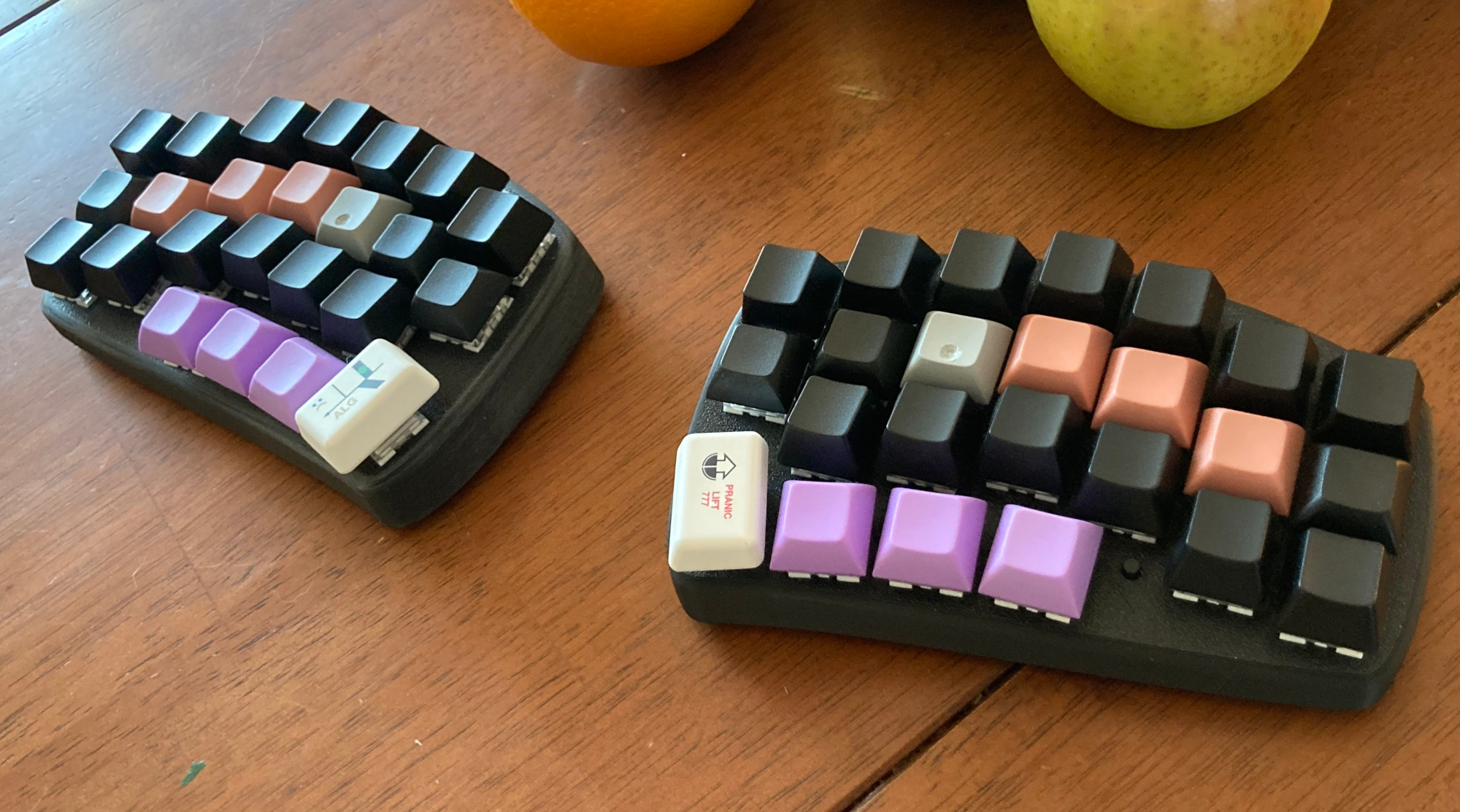
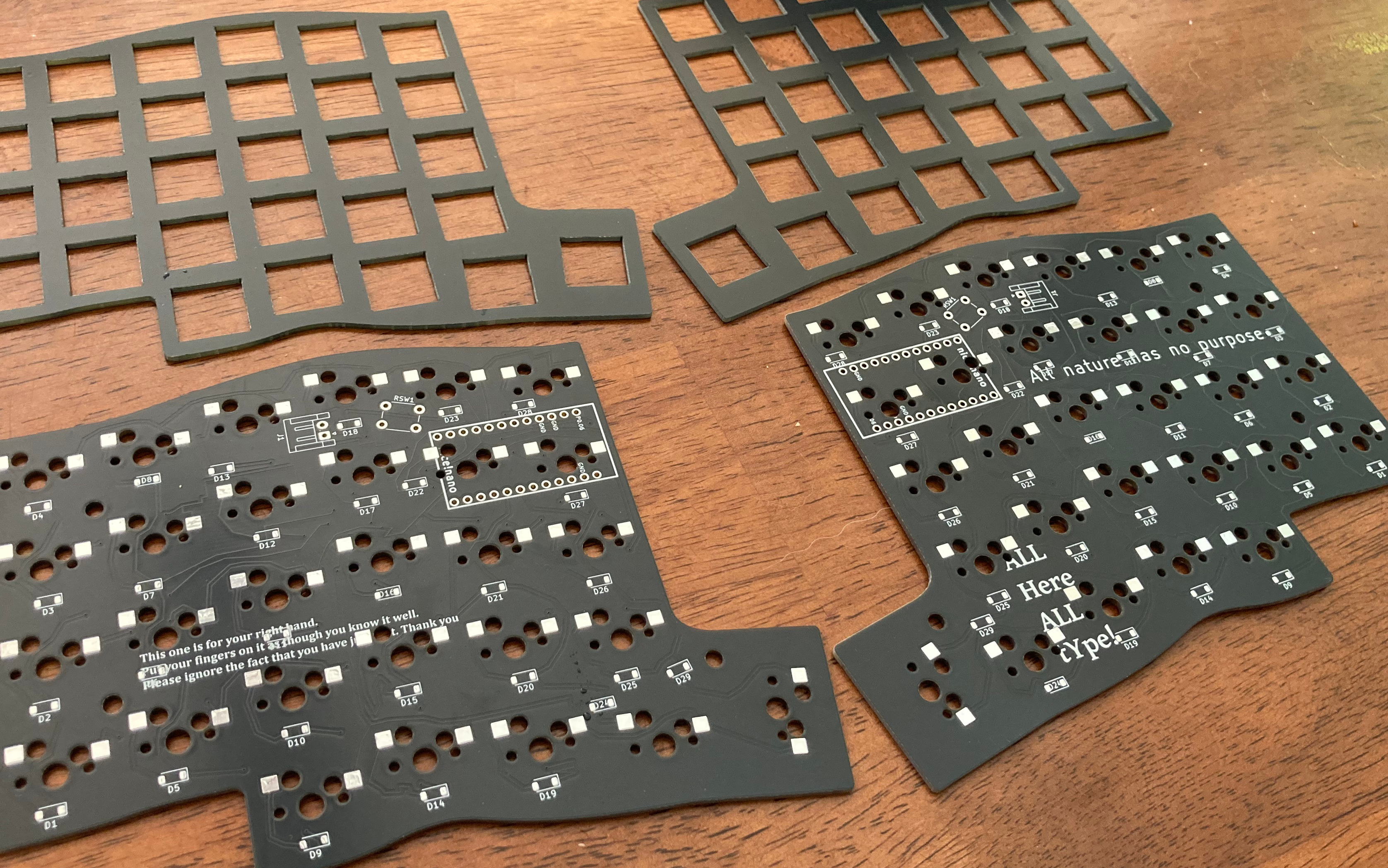
I made the keyboard to get familiar with the process and feel–to experiment with what I wanted. And it was the fist ortholinear ergonomic keyboard I’d used and I quickly found ways to improve it. So I made this:
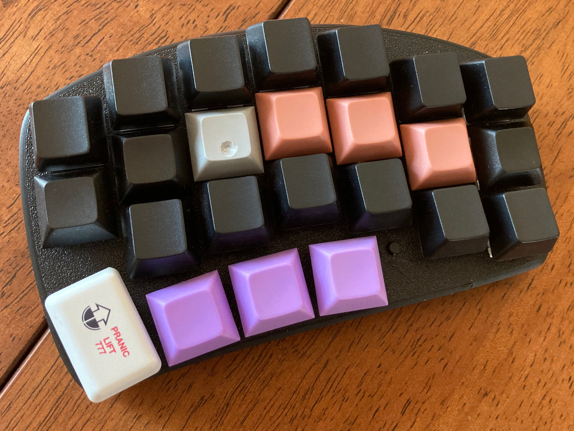
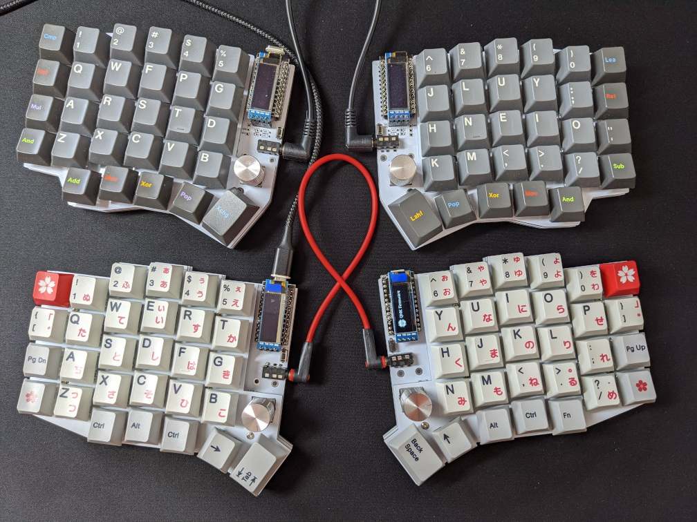
I eliminated the number row, thinking it would make more ergonomic sense to use layers more efficiently instead. I also staggered the pinky rows quite a bit. On my first iteration I kept mashing other keys while trying to type P or Q (hence the strange key cap profiles on the original–which did help a bit). I made it “unibody”, shifted and splayed out those thumb keys, and added rotary encoders. (The left one is for left and right arrow keys and the right one is for up and down. Clicking them in toggles ctrl+L/R and PgUp/PgDn.) Another big upgrade was going from Cherry MX brown switches to Kailth silent box browns. (No I don’t understand these bonkers naming conventions either) It feels much better.
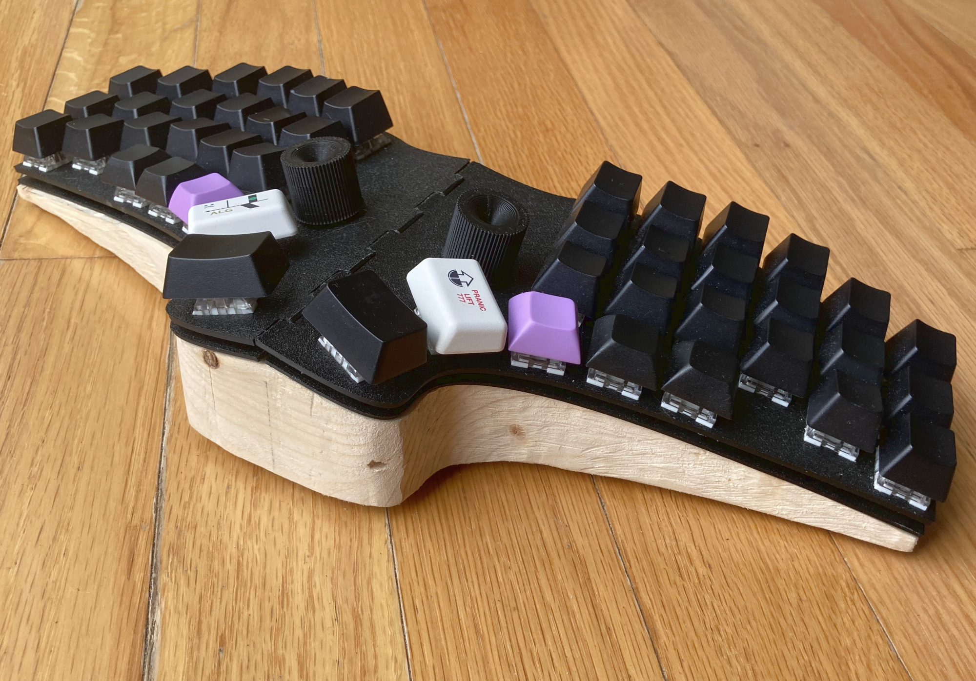
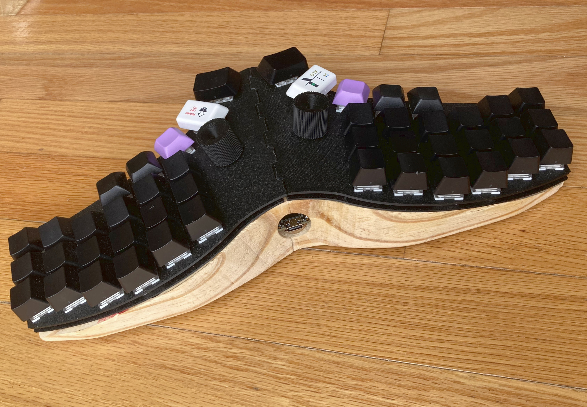
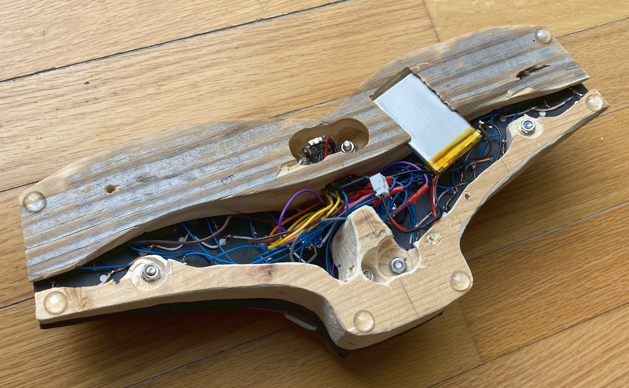
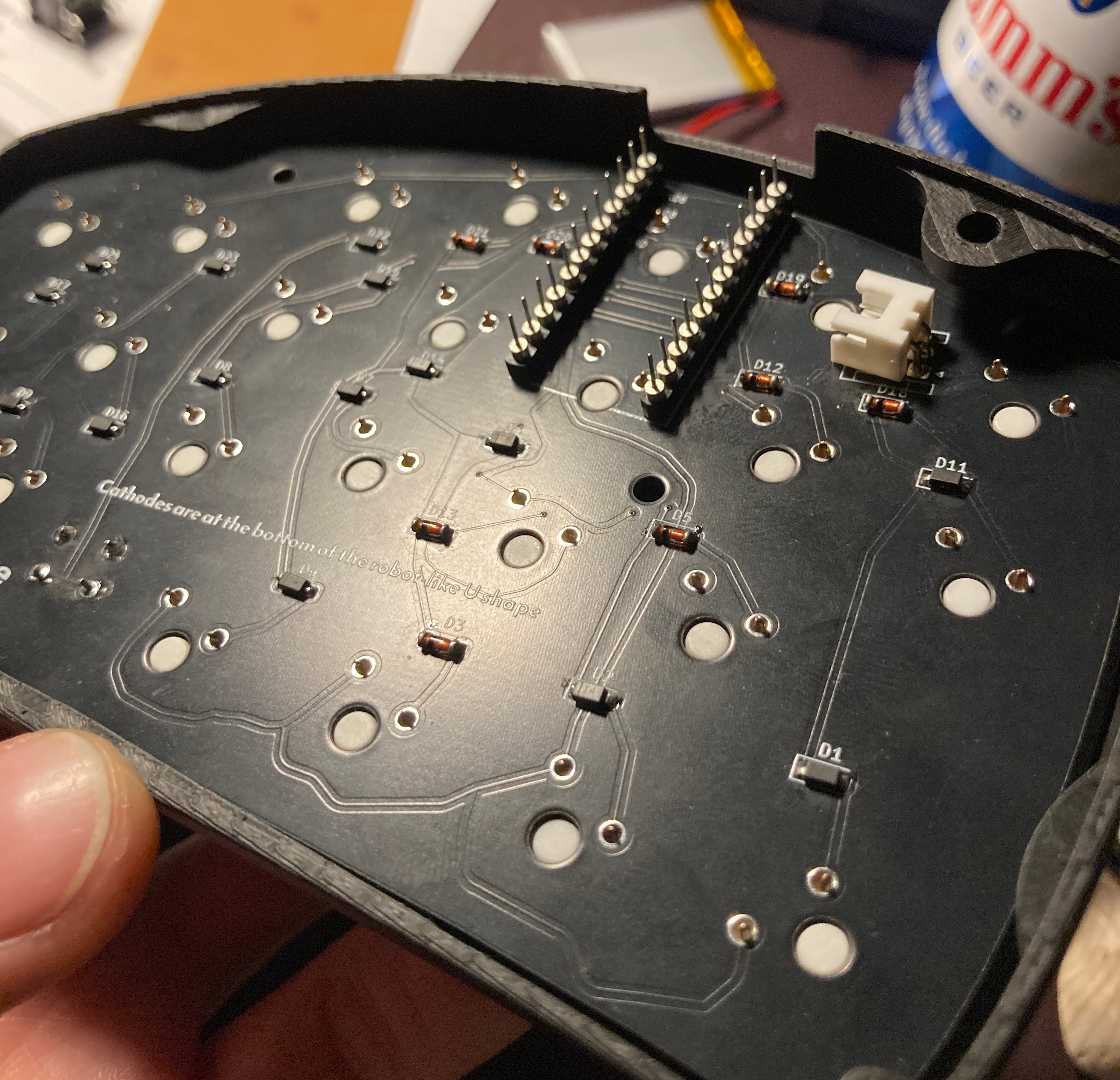
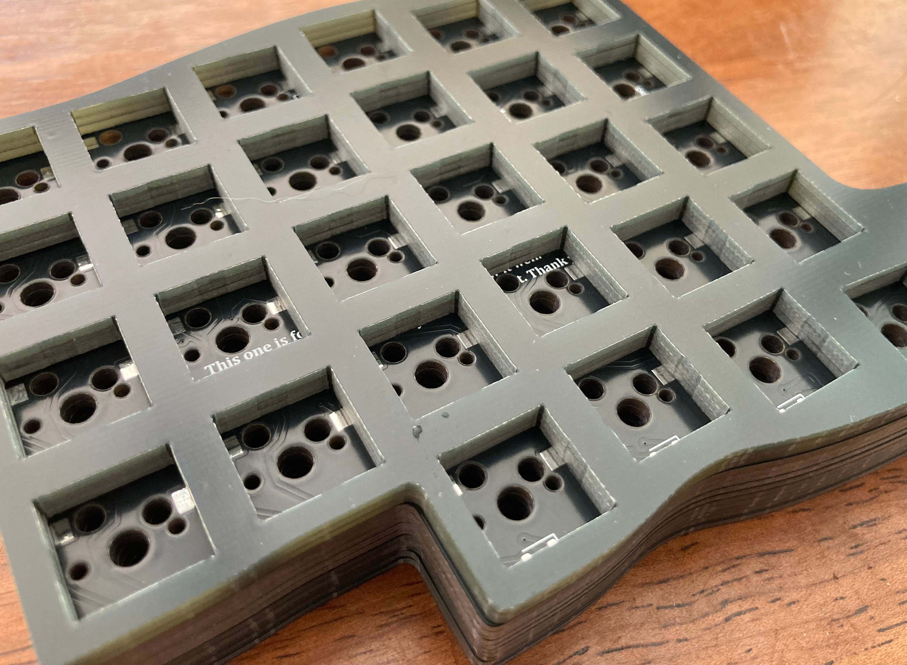
The second design process was a bit insane, basically I made a little drawing and designed it as I went. I hand-wired this one because why not and I wanted to make the body out of wood, mostly because I knew how and big 3D printed things generally look ugly and dumb.
I never really used the rotary encoders much, I usually just used the arrow keys on a layer, although when I remembered they were there it was fun and intuitive. I also never found a good use for those innermost keys on the thumb cluster. The one on the left is a macro for ctrl+left and the one on the right does nothing. Even the next key up on the right is a useless shift key. So I see this keyboard now as an experiment in maximalism, ha.
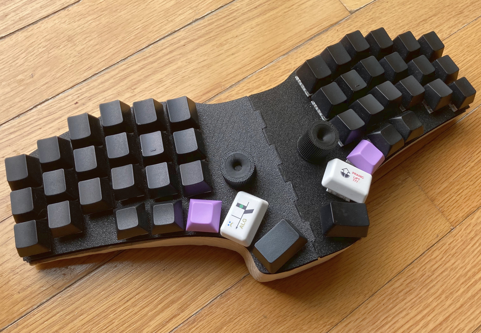
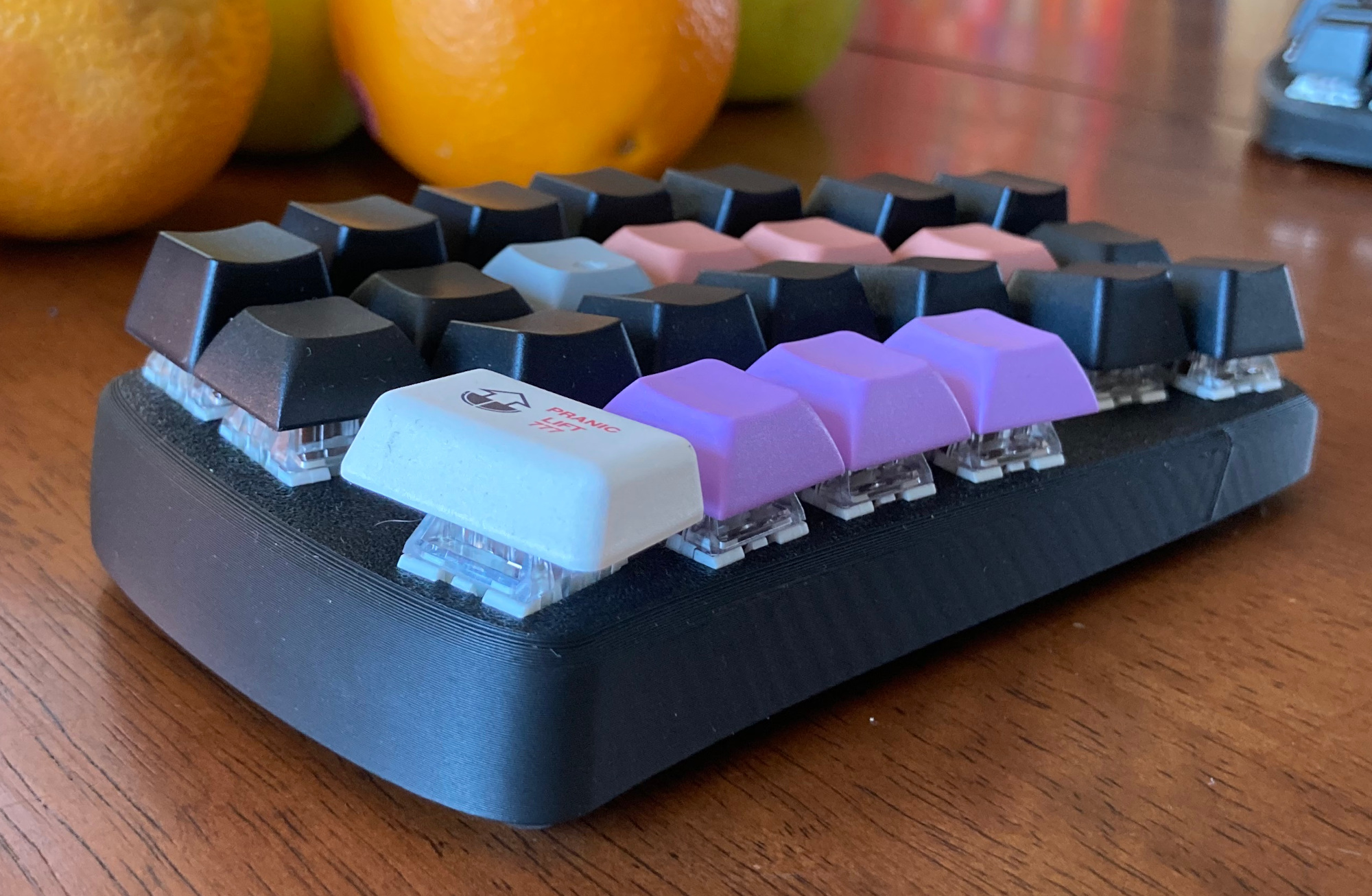
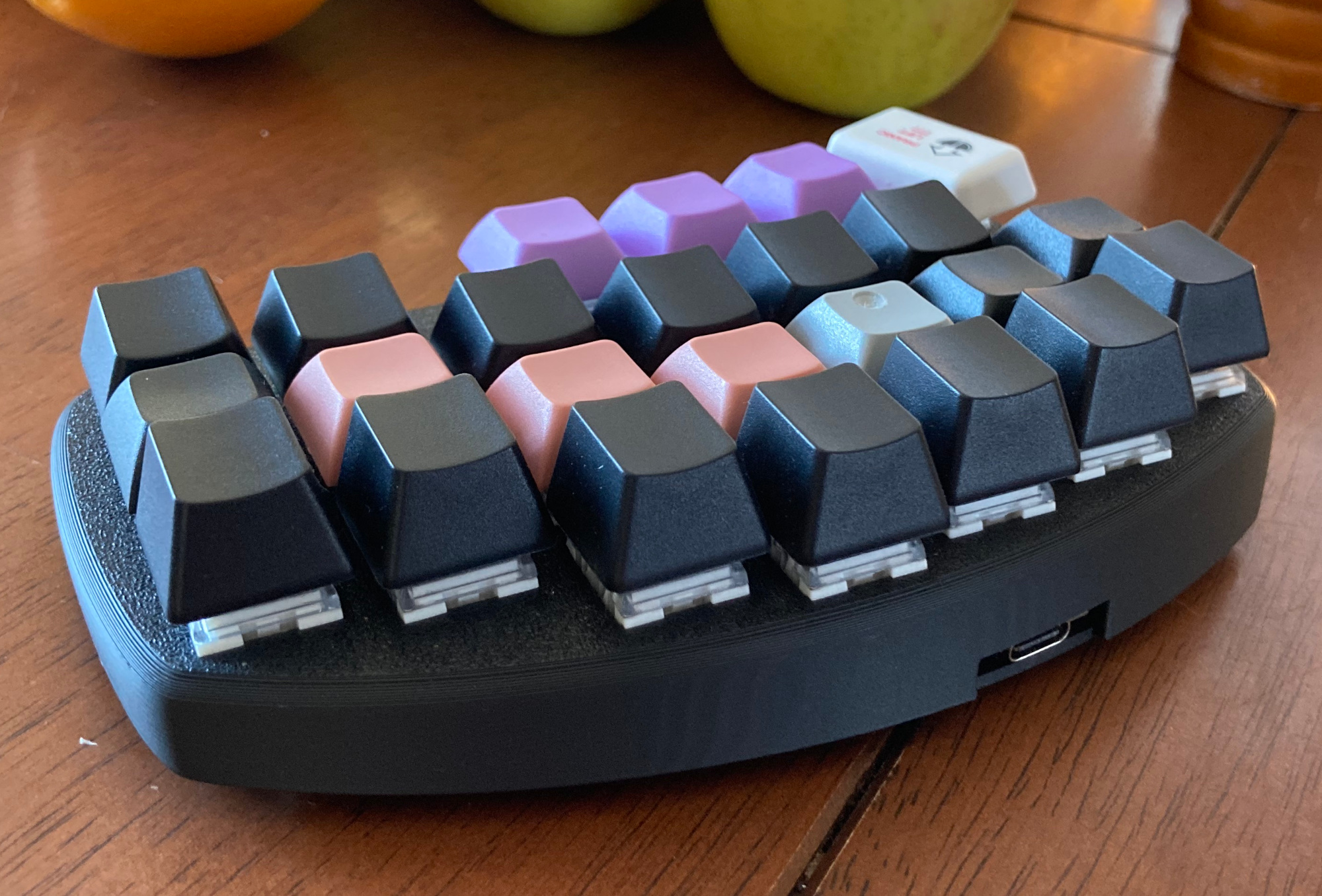
My third iteration is complete and I’m typing on it now. Do you like how it types? I think I’ll keep it for a while. It’s nice and low, probably has about the right amount of keys and pinky stagger, and I even threw in a couple extra keys in the middle for fun.
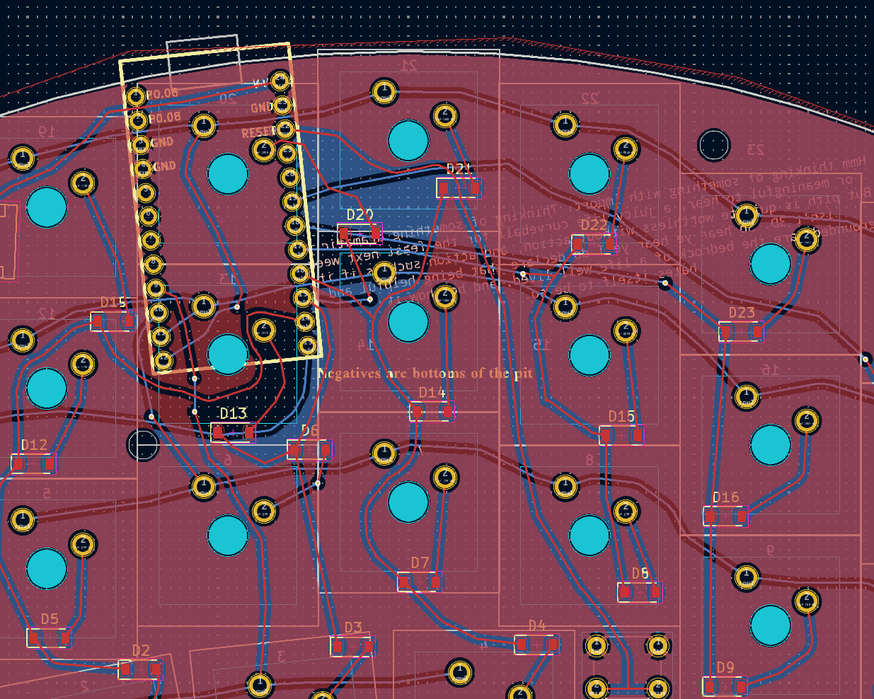
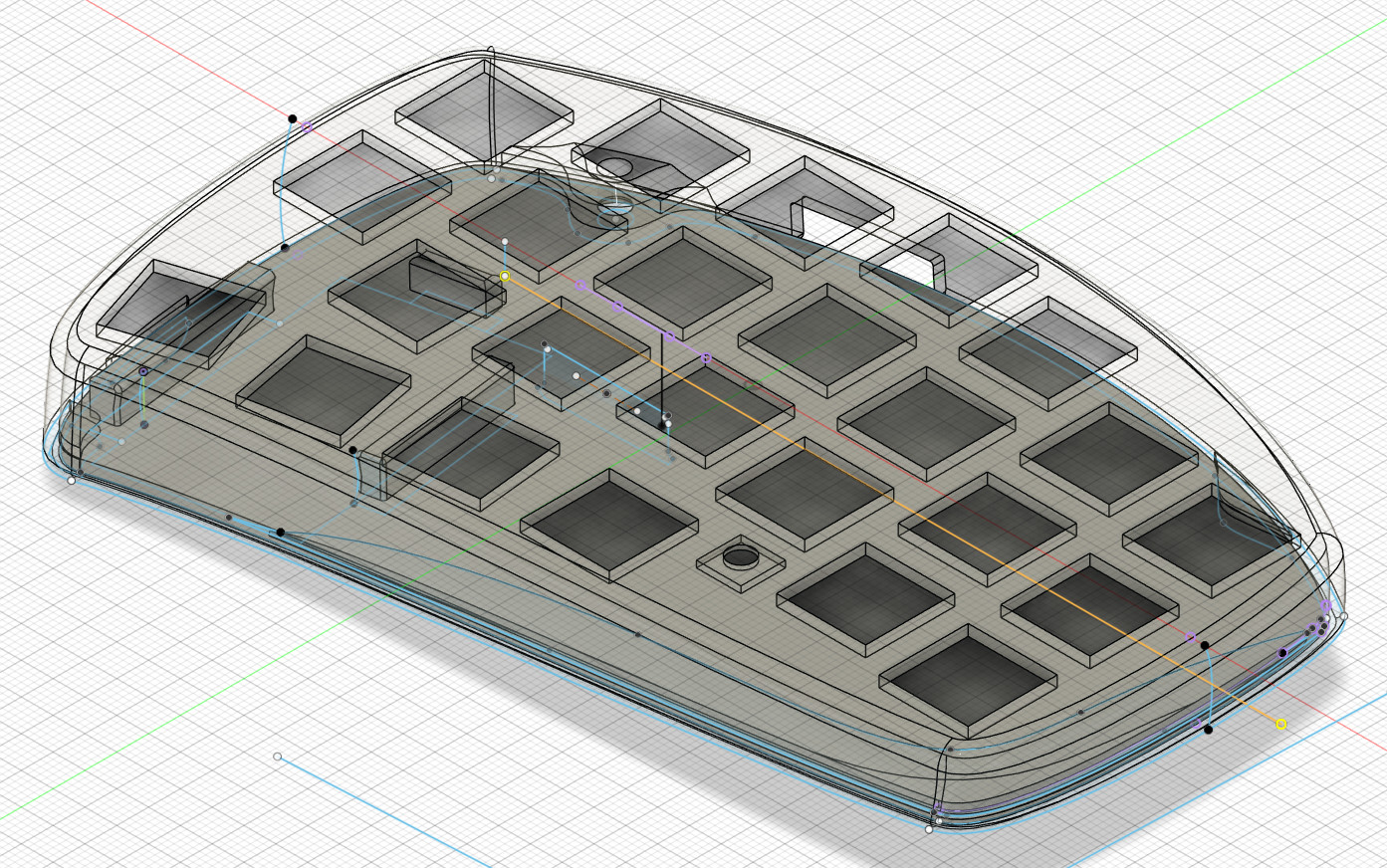
The most challenging part with this build was the case I’d say. For some reason it was important to me to have the front panel contiguous with the sides so it looks like a shell or something. So I had to both fit the PCB in from the bottom and mount the bottom plate on. The tolerances are pretty tight too, so I learned a lot about autodesk fusion and made a few rough drafts.
Now I’m on to another kind of silly and difficult journey: learning how to type using Colemak-DH. It’s fun! I’m using standard keyboards all the time at work so we’ll see how my brain adjusts to being uh… not quite bilingual.
changing my keyboard part 1
Ah the world of split ergonomic keyboards. Where one can get lost for days reading barely seen reddit posts and learning all about how programmers type even though you’re not one.
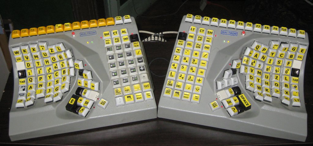
First of all, what’s wrong with a standard keyboard? Nothing! It works, it has all the keys. You can learn how to use it fast and efficiently. It seems most of (?) the people who are into this are motivated by repetitive stress injuries, which also leads to alternative layouts like Colemak. But I’m motivated purely by interest, I’m just here to have fun (thankfully), and the nerd in me perks up when I read about the questionable utility of the standard keyboard. I’ll stick with qwerty, but there are many functional ways that a standard keyboard is just kind of silly. I only hit the large spacebar with my right thumb. I never hit right shift. Or caps lock. Or these things < >. Also they’re pretty.
A few years ago, I taught myself how to touch type after hunting and pecking for about 20 years. I’m still not good at it but it really got the juices flowing around that neuroplasticity thing I’ve been hearing about. And around things big and small that I take for granted too. And there’s a lot of convergence here with many things that I enjoy. Designing is always fun, designing useful things is even more fun, and designing useful electronics is probably the best thing.
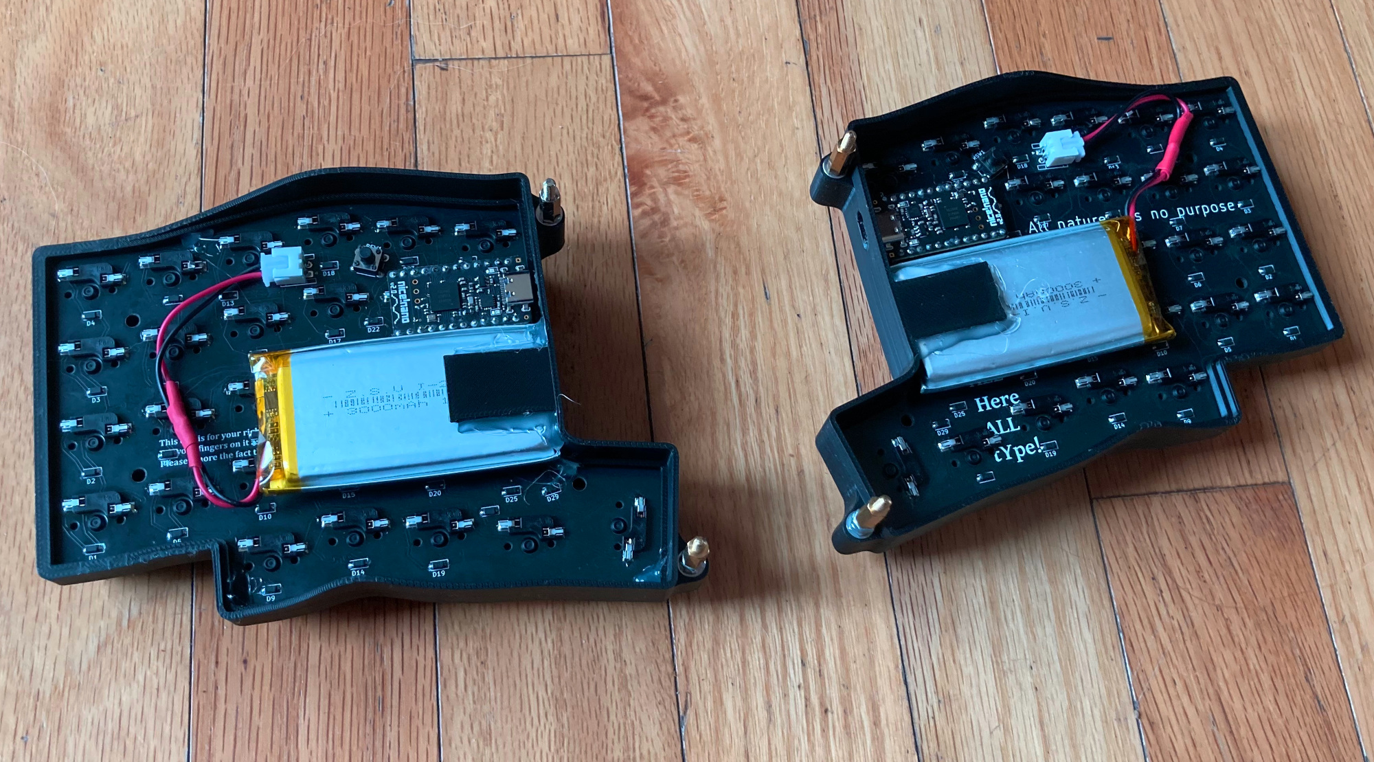
So where to start? I didn’t want to go crazy, nor did I want to go crazy, so 58 keys total seemed manageable (a full keyboard with the numpad and stuff is 104 keys), especially when you take into account layers which act like the shift key but completely change the layout. I watched this video and loved the approach–wireless, a hidden microcontroller and battery, and no need for LEDs.
I quickly stumbled upon some software that a lot of people swear by called Ergogen. It was fun to use and helped me get my head around the layout and spacing of the keyboard. But probably the biggest drawback for me is that the end result of using this program is PCB footprints spaced out properly in KiCad. No schematic, no traces drawn. So I used Ergogen to get my layout into kicad then reverse engineered it to get the schematic (not very complicated) then laid out the PCB from there. But hey if Ergogen works for you, go for it! I understand that not everyone wants to learn KiCad either, and I’m sure there’s some functionality to it that I hadn’t tapped.
Anyway there’s plenty of information out there so I’m not going to explain ulnar deviation or layers or home row mod-taps. PCBs and parts are arriving on the regular so I’ll let you know if it was a horrible waste of time or not.
upgrade
What up Internet? It’s been a minute. Time for me to brag!
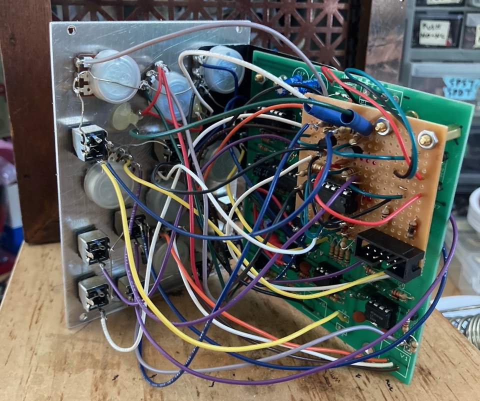
A while ago I posted a pic of this modular lunetta in progress, and here it is now. And also a while ago I built a bunch of stuff and put it in there. And then also a while ago I made a tape of very noisy playing with it. So I pulled it out, gave it a light dusting, and took a picture for you, dear reader.
I incorporated a pipsqueak of course, which is a wonderful way to get insane voltages throughout the system. I added range knobs too so it can be more like an LFO. Some utility stuff, some logic gates, a stereo panning mixer, more LFOs, a melody generator, and in the upper right a motor that rings two bells from a telephone. I used another circuit from mroztronium that he was kind enough to share with everyone in the world. It takes pulse inputs and reads them in a sluggish or not so sluggish way to spin a motor and it’s a lot of fun. Now if only physical bells had volume knobs.
Summer in Maine is a fun and busy time and I’m grateful for a whole lot more than I could write here.
I did a slightly-risky-but-ultimately-I-knew-it-would-be-fine thing and decided to forgo having an employer per se this summer, which has allowed me to do a number of things–one of which is to take stock. I feel like I never regret giving myself space to think or to have time alone, and it’s been subtly fruitful in that way.
Another thing it allowed me is a little bit more agency in my financial life, which is a weird way of saying that I’ve been working for myself. Doing electronics repair! (I currently have the comically heavy and enigmatic Akai MG 1212 sitting in pieces in my too-small-for-that bedroom.) So far it’s been relatively sustainable, but I have no idea if that will be true when it comes time to pay taxes. It’s taken precedence over synth DIY and the other day I started building a Bi-N-Tic filter on strip board and was pleasantly reacquainted with my joy of the process. Of course it’s somewhat similar to repair but leaving the financial aspect aside was a bit of a relief (I guess I was losing money but it wasn’t very much).
And let’s see, what else? There have been important people and moments and frustrations and sighs, but if you want to hear about that you’ll have to get at me in person. Sorry, internet, my hands are tied. Bye!
downgrade
The past year or so I’ve been very tepidly exploring avenues for sharing more online. No one would know that by looking at the amount or subject of content I produce, but it’s been in the back of my mind for a minute. I want to share more of what I’m doing creatively, and the reason for the hesitation is that doing so pretty much requires participation in the attention economy, opaque algorithms, terms of service that I haven’t read, and the forsaking of some amount of privacy.
Behold the low tech web ring. See also: this website and this one. Although I’ve had a blog for many years it didn’t feel like much of a platform, and that’s because I didn’t treat it like one. It’s not as immediate as the socials, but I have infinitely more control both in what the visitor sees, and what I am able to produce.
Basically what I’ve gone and done on the back end of this site is downgraded. I went from using WordPress to using Jekyll and GitHub pages. It’s a little more difficult to implement. There aren’t as many plug-ins available. But it’s fun, and instead of installing a theme and deleting most of the CSS I can write the code that I want to see. Yes this site looks and feels almost exactly like my old site, but just know there’s way more enthusiasm underneath.
In any case I hope you enjoy the lack of ads and not needing another password to be here and participate. Stay tuned.
low-tech talk
Just spent a minute watching this wonderful and inspiring talk from Devine of hundred rabbits. Boat punk nerds. It really got the juices flowing around doing things the slow hard way, and the importance of autonomy and curiosity.
All the technical stuff went far over my head but I like that. Also the pictures were pretty.
workbench tour
Made a little video about my electronics workbench!
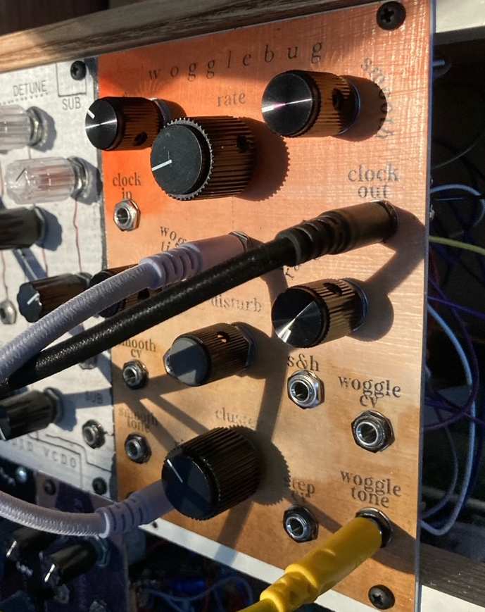
wogglebug
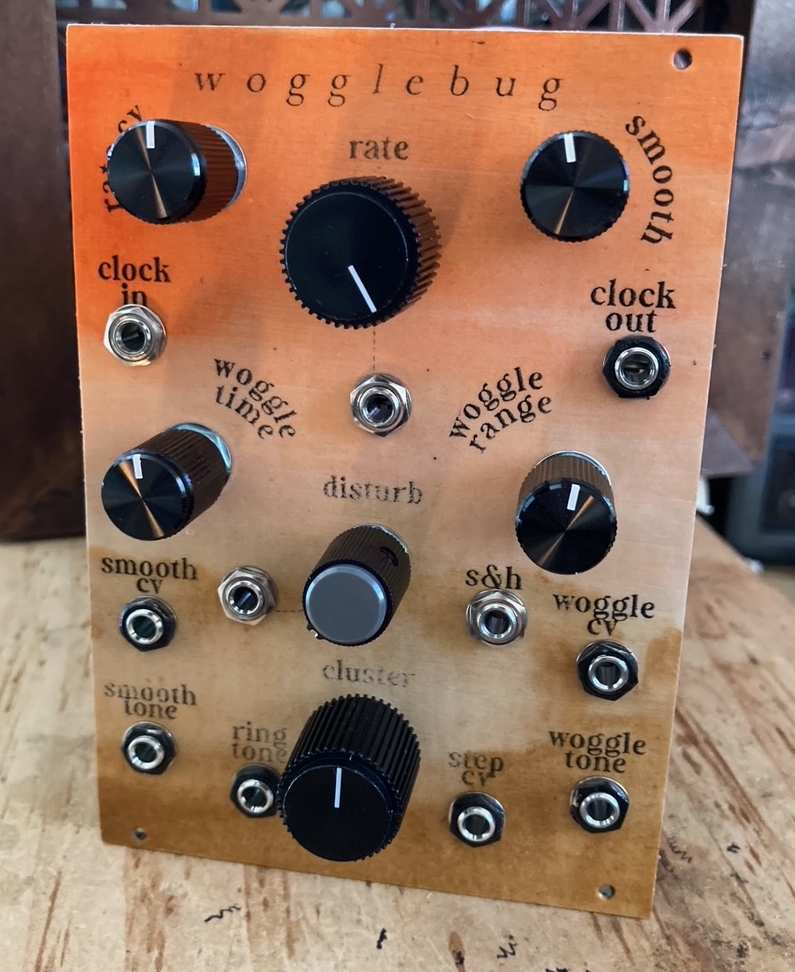
What is it and how does it work you ask? Jesus I don't know. I know it sounds great though, and has that healthy-but-not-unwieldy amount of instability that I love. There are two oscillators and a third "ring modulated" output from them, two voltage-followy CVs from the oscillators, as well as an internal sample and hold out. You can modulate the clock and it has some great internal cross-modulation. See the Wiard Dual Wogglebug for a better explanation.
So having gone down this rabbit hole I'm writing this now so that hopefully your jaunt down there isn't so fraught. I bought the PCB from synthcube and started looking at schematics and mods. First there's the Grant Richter #3 standard schematic, then there's an update with some improvements (like buffered outputs--this one is what the MOTM PCB corresponds to). Then there's Dave Brown's corrected version of that redraw, some minor errors on the PCB, and those are all for +/-15V systems. Does your head hurt yet? Because then there's the Erica Synths redraw which does have correct resistor values for +/-12V systems, but also includes some other errors.
So here I've redrawn it again! Just to make things more confusing. So this schematic and BOM apply to the MOTM format wiard wogglebug PCB currently sold by synthcube, and has correct resistor values for +/-12V power.
Wogglebug Schematic
Corresponding BOM
R42 and R43 can serve as attenuators for the smooth and woggle CV output levels respectively. Linking these with wire (zero ohms) yields a signal from about 0-9V.
The 3 numbers of the potentiometers correspond to their lug wiring. This isn't always clear on the PCB so you may have to follow some traces. Oh and I couldn't find this anywhere, but the board measures 3 7/8" x 4 5/16" (or 9.9cm x 10.9cm). It was a tight fit!
So that's what's up for building a standard wogglebug from the available PCB, and here are some additions and mods not present in the above docs.
Pugix made his own wogglebug on protoboard with many interesting differences. I've included the disturb circuit from him, an optional input (or two) that's mixed into the woggle range. I've also added two LED drivers.
I've inverted the clock (outlined here and here) and interrupted the sample and hold trace on the PCB with a switching jack and diode protection. It's helpful to put a 4.7nf capacitor from V1 lug 3 to ground also.
I've seen a couple people asking about making their own dual vactrol (the VTL5C3/2). Yes, it's very doable! Put two LDRs up against one LED and wire the LDRs in series. Like this!
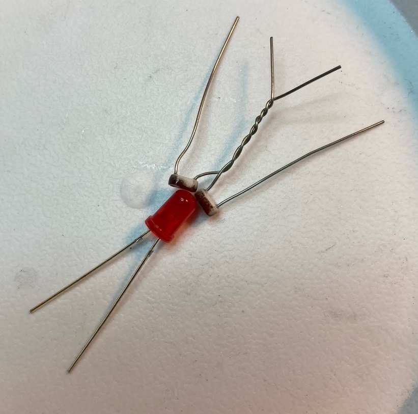
So yeah, holy shit. Time to go touch grass. I really am grateful for all the different versions out there because I both pulled and learned from all of them. And to people talking it out on various forums from back when these things were cool (like 2008, ha). Anyway, go build one!
phase 13 lunetta
Just wanted to share my build progress with this bonkers modular lunetta.

If you want to fart around making noisy weird circuits go to the Lunetta forums over at electro-music.com and just start reading. It's a gold mine. I've found immense inspiration from everyone posting there, from veterans who've gone on to make careers out of this stuff to noobs asking about voltage regulator pinouts.
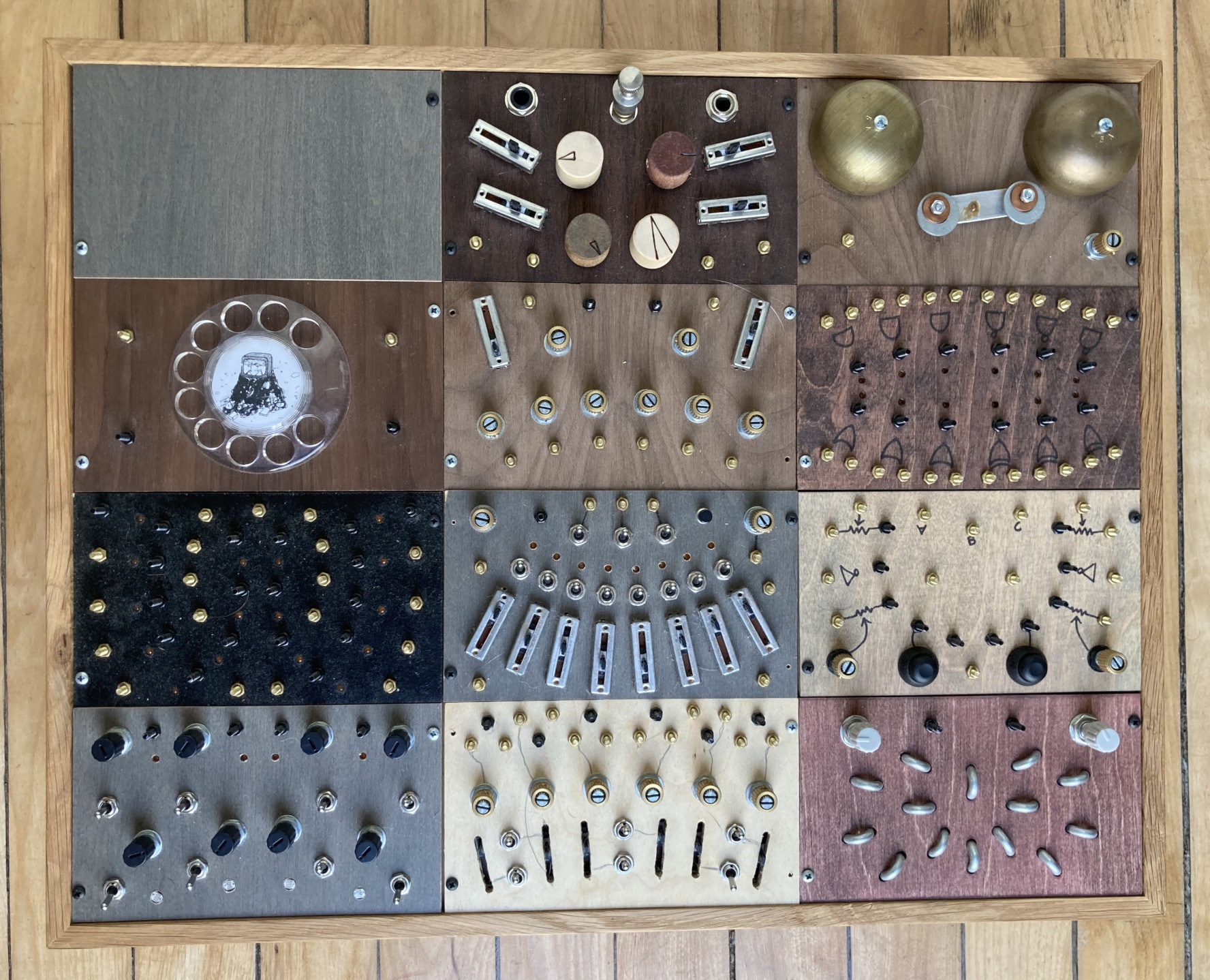
Given the amount of possibilities the modular approach was the only one that made sense for me. It kept my head from spinning. And since my 3U setup is mostly metal panels, and I have access to wood scraps, I thought I'd give that a go. The patch points are made with bolts. Golds are ins and blacks are outs. I like the grid-like uniform look of the Buchla 100 series and I thought if the panels were more wide than they are tall it would lend itself well to sequencers and the like, make it feel a bit more keyboardy for lack of a better term.

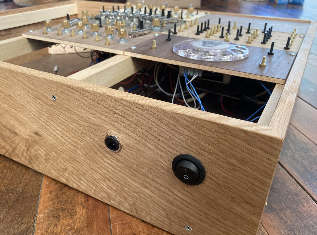
Anyway, phase #13 includes (clockwise from bottom)
- Six 40106 oscillators with a diode CV and a vactrol each.
- (Symetrically, from the outside in) two R2R ladders, two 4015 shift registers, and in the center is a 4040 clock divider.
- This is a goddamn rotary phone wired up to bolts. No soldering required. It's kind of gimmicky and very ridiculous and fun.
- Two LM358 lowpass filters. There are two frequency CVs and one vactrol resonance input each. Here's the schematic. I built a few filters and liked the sound of this one the best.
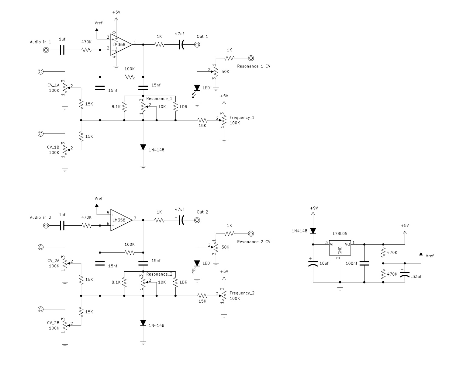
- This is a 4051 sequencer with its own internal oscillator and diode CV input. Messing with the ABC inputs is a lot of fun.
I don't have a ton to offer at the moment in terms of new circuits or ideas but here are a couple things I've gleaned.
C pots or antilog pots work really well with 40106 oscillators. Because it oscillates based on the exponential charging and discharging of a capacitor an antilog pot gives a linear response.
Another tiny circuit I like a lot is making a little OR gate on inhibit inputs so you can have a "trigger or gate" response to the same pin. Like this!
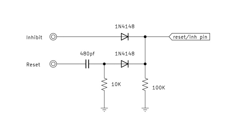
Anyway, thanks for reading!
tascam porta two manuals
The Tascam Porta Two Ministudio service manual:
And the owner's manual:
I like this unit a lot. Weird flat rubber knobs. I guess they were still figuring it out in the 80s.
cable rack
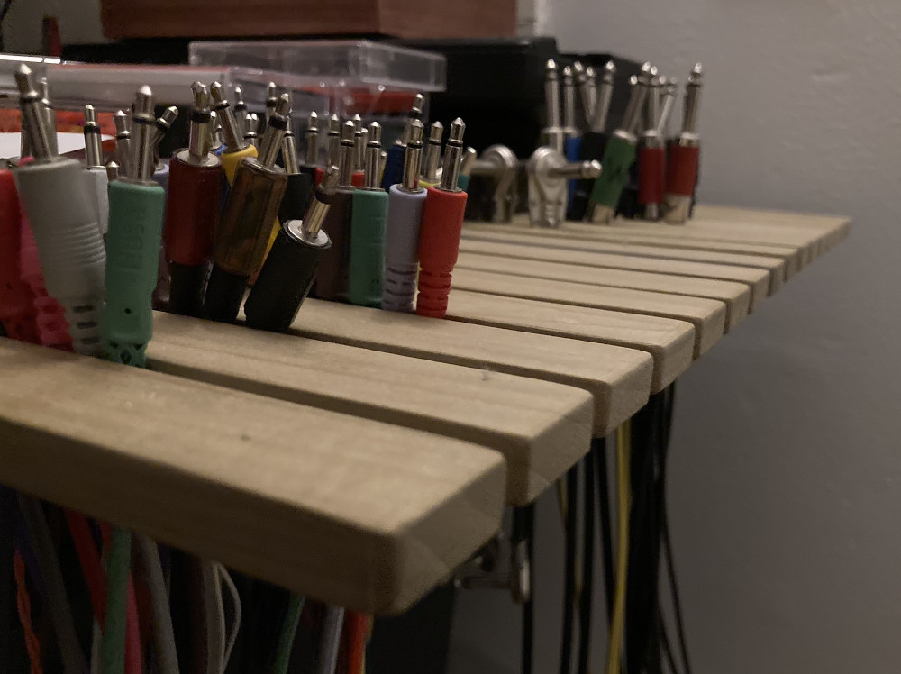

I made this out of two wide chunks of poplar (unmounted it looks like a comb ya know?) The tongues are one inch wide, the small cables get 1/4" slot, the big boys get 5/16".
on link rot
I recently went to an old blog that I like but is never updated. It was made by a circuit bender, a really good one, who would add loads to the circuitry/controls, and the results were always aesthetically pleasing. I'd visit probably once every six months to a year, and having learned a bit about electronics in that time I could glean a little more from the writeups and half-schematics.
And now it's gone. Deleted!
Of course the creator of the site had no idea I'd found it so useful and inspiring, and there are fees for hosting a website. And of course there's the wayback machine. But more and more I'm finding wonderful old sites with dead links and broken images.
There are no broken images on social media, however. Most blogs I'm thinking of died in the mid-late 00s. Seeing a crazy DIY synth on the socialz™ begs the question for me: what did the maker find so exciting about this thing in particular? How did they get into this? Care to share any schematics? And why do I, the user, feel like scrolling instead of actually asking these questions?
I am (like a lot of people right now I imagine) sensing a lack of community. And of course it's not necessarily my intention that fosters that, but the tools I use.