yet another benjolin build
A wild beast with no patching needed! A giant module with dead eyes! A sea of confusion that came together in the end!
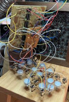
For these mods I mostly refered to the casper electronics page (with some changes I’ll mention) and Forest Caver’s schematics. I also used the level reducer for the bits out by Macumbista, mentioned in the same thread as the PCB layout here. The mods are on a stripboard which you can see mounted in one of the last pictures below.
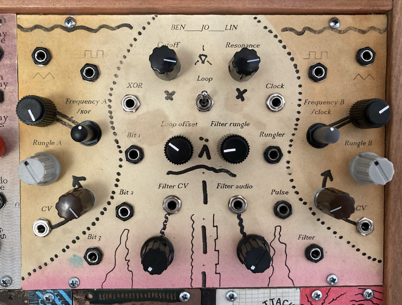
To eliminate all the switching for the rungler in the casper version I changed a couple things. For starters I used the loop offset mod from Forest Caver. Then I normalled the standard connections through the XOR/clock comparator to the rungler mentioned in the casper version. (Okay I went from two switches to one, but it’s much less complicated.) If you’re using the osc 1, osc 2, and filter cv inputs you don’t need the 51k resistors shown on the old casper page, they’re already on the board. (See O1CV, O2CV, and FCV labels on the original silkscreen.) And according to Mr. Edwards himself the pulldown resistors after the comparator opamps are completely unnecessary.
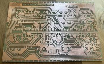
I used the toner tranfer method for etching this circuit board and sadly I have no advice for you. There’s so much info out there, it’s probably best to dive in. Also my first two attempts were utter failures, little to no transfer, and the third came out almost perfect, so…

The front panel design was a bit of a creepy mystery. After the layout I was experimenting with lines to divide up the oscillators and functions, a scrapped one just looked like a basketball. But curvy lines around the oscillators made a little bust so I drew a face and voila. It bears a striking resemblance to a fucked up part in the videogame “SOMA” where someone is being kept alive against their will by a machine. There’s my creepy subconscious for ya.
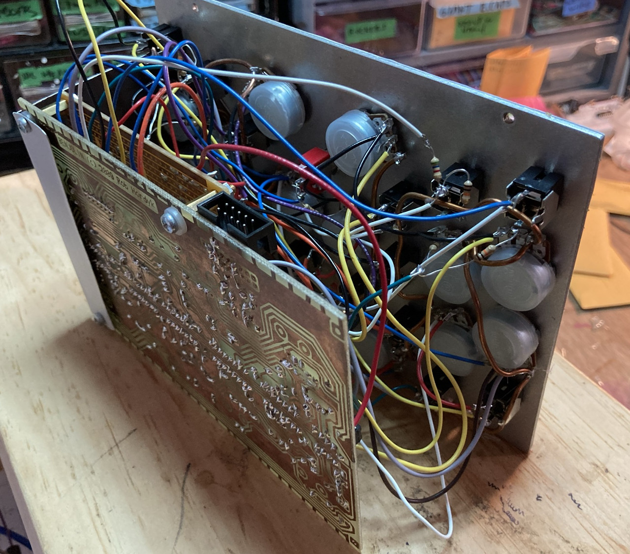
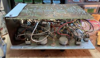
I opted to mount the PCB parallel to the front panel because it’s the only way it’d fit. I wired the ground at the panel with 14 gauge copper wire so the components would stay rigidly in place, and then I could take the metal panel off and have more angles to solder from. It looked cool, but I still ended up mostly just bending the mounting bracket out to wire it (see the second picture).
I made a schematic of all the mods I used. Here it is. Oh and I voltage dropped the pulse outs (osc 1, osc 2, and PWM mix) a little. Also I never use the fine tune knobs so. Sounds: