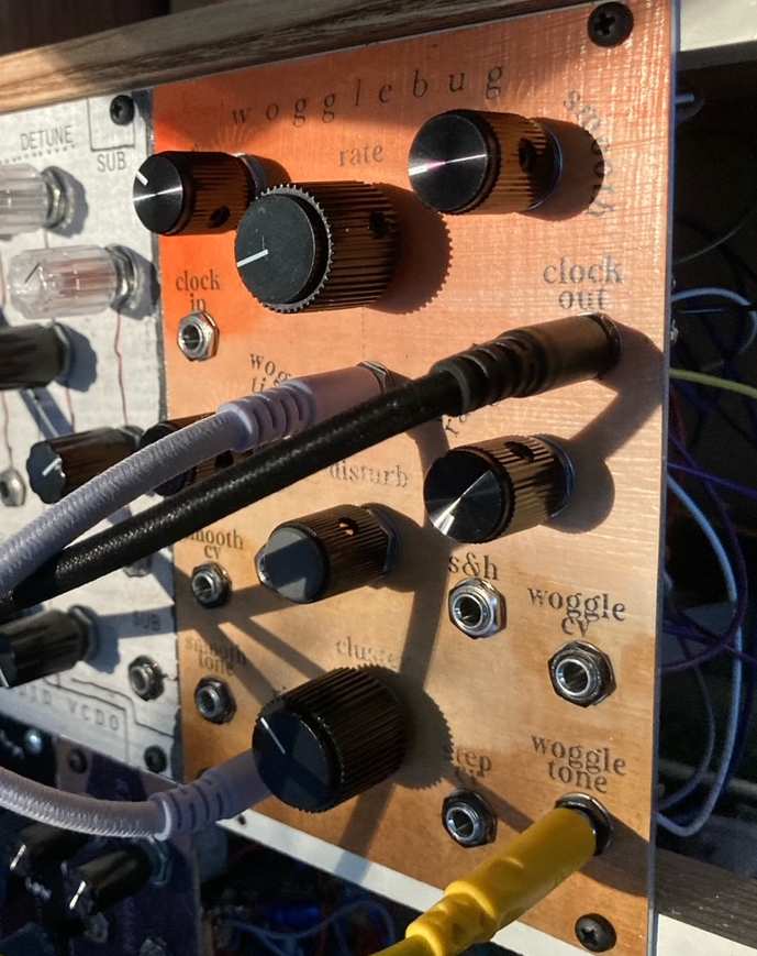
wogglebug
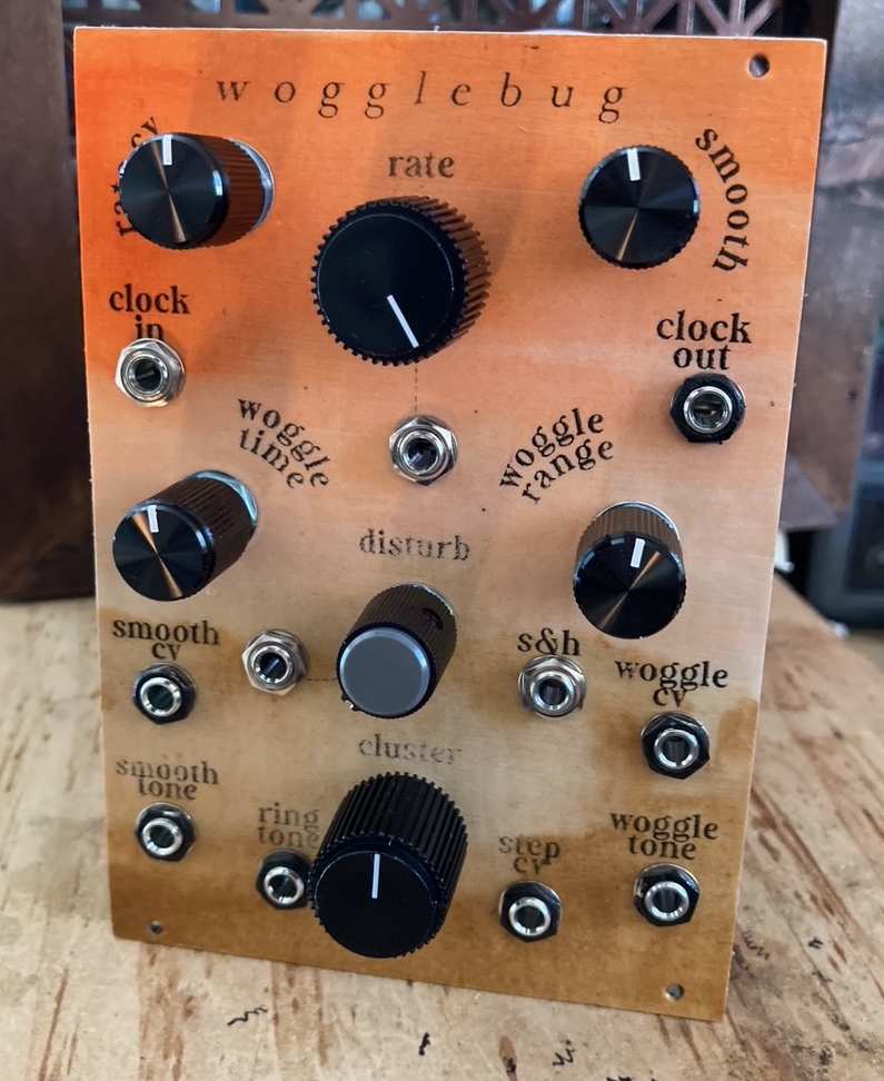
What is it and how does it work you ask? Jesus I don't know. I know it sounds great though, and has that healthy-but-not-unwieldy amount of instability that I love. There are two oscillators and a third "ring modulated" output from them, two voltage-followy CVs from the oscillators, as well as an internal sample and hold out. You can modulate the clock and it has some great internal cross-modulation. See the Wiard Dual Wogglebug for a better explanation.
So having gone down this rabbit hole I'm writing this now so that hopefully your jaunt down there isn't so fraught. I bought the PCB from synthcube and started looking at schematics and mods. First there's the Grant Richter #3 standard schematic, then there's an update with some improvements (like buffered outputs--this one is what the MOTM PCB corresponds to). Then there's Dave Brown's corrected version of that redraw, some minor errors on the PCB, and those are all for +/-15V systems. Does your head hurt yet? Because then there's the Erica Synths redraw which does have correct resistor values for +/-12V systems, but also includes some other errors.
So here I've redrawn it again! Just to make things more confusing. So this schematic and BOM apply to the MOTM format wiard wogglebug PCB currently sold by synthcube, and has correct resistor values for +/-12V power.
Wogglebug Schematic
Corresponding BOM
R42 and R43 can serve as attenuators for the smooth and woggle CV output levels respectively. Linking these with wire (zero ohms) yields a signal from about 0-9V.
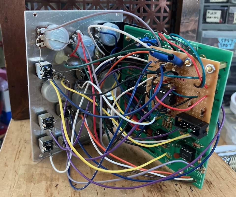
The 3 numbers of the potentiometers correspond to their lug wiring. This isn't always clear on the PCB so you may have to follow some traces. Oh and I couldn't find this anywhere, but the board measures 3 7/8" x 4 5/16" (or 9.9cm x 10.9cm). It was a tight fit!
So that's what's up for building a standard wogglebug from the available PCB, and here are some additions and mods not present in the above docs.
Pugix made his own wogglebug on protoboard with many interesting differences. I've included the disturb circuit from him, an optional input (or two) that's mixed into the woggle range. I've also added two LED drivers.
I've inverted the clock (outlined here and here) and interrupted the sample and hold trace on the PCB with a switching jack and diode protection. It's helpful to put a 4.7nf capacitor from V1 lug 3 to ground also.
I've seen a couple people asking about making their own dual vactrol (the VTL5C3/2). Yes, it's very doable! Put two LDRs up against one LED and wire the LDRs in series. Like this!
So yeah, holy shit. Time to go touch grass. I really am grateful for all the different versions out there because I both pulled and learned from all of them. And to people talking it out on various forums from back when these things were cool (like 2008, ha). Anyway, go build one!